Kolega
4 MIN QUICKSTART GUIDE:
USER INTERFACE

Navigation Panel:
Located on the left side of the main window, the navigation panel provides access to all workflow steps required to generate solutions. Each step is clearly outlined and sequentially organized for user guidance.
Main Canvas:
The central workspace displays geometric objects and visual elements. Users can interact with and manipulate these objects directly within this area.
Properties Panel:
Positioned adjacent to the main canvas, the properties panel allows users to view and modify attributes of selected geometric objects.
NAVIGATIONPANEL
The program is navigated using the navigation panel, located on the left side of the main window.
This panel contains all the steps users need to follow to generate the appropriate solutions.
01 START PROJECT
Create New Project:
To start a new project, select the New Project tile from the Home screen.
You will be asked to enter a name for the project (this will also be used to name the project folder), a short description (optional) and location where to save the files. Once these details have been completed, the project will be created and Kolega will proceed to the Site Info screen.
Open Existing Project:
To open an existing project, select the "Open Project" option and navigate to the project folder in the dialog window. Make sure to open the folder itself (not just select or highlight it).
Open Example Project:
The program includes three sample projects, which are an excellent starting point for understanding how the software works. These examples vary in complexity.
The more complex the project, the more powerful the computer is required, and the longer it may take to process.
HOW TO PREPARE THE DESIGN SPACE
There are 4 types of elements which control the buildings generation process:
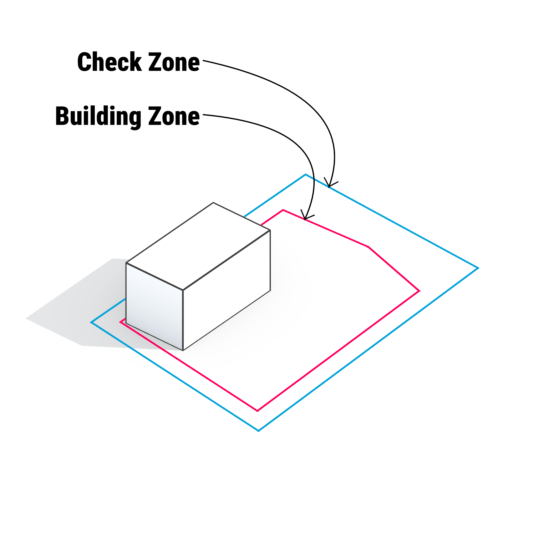
CheckZone:
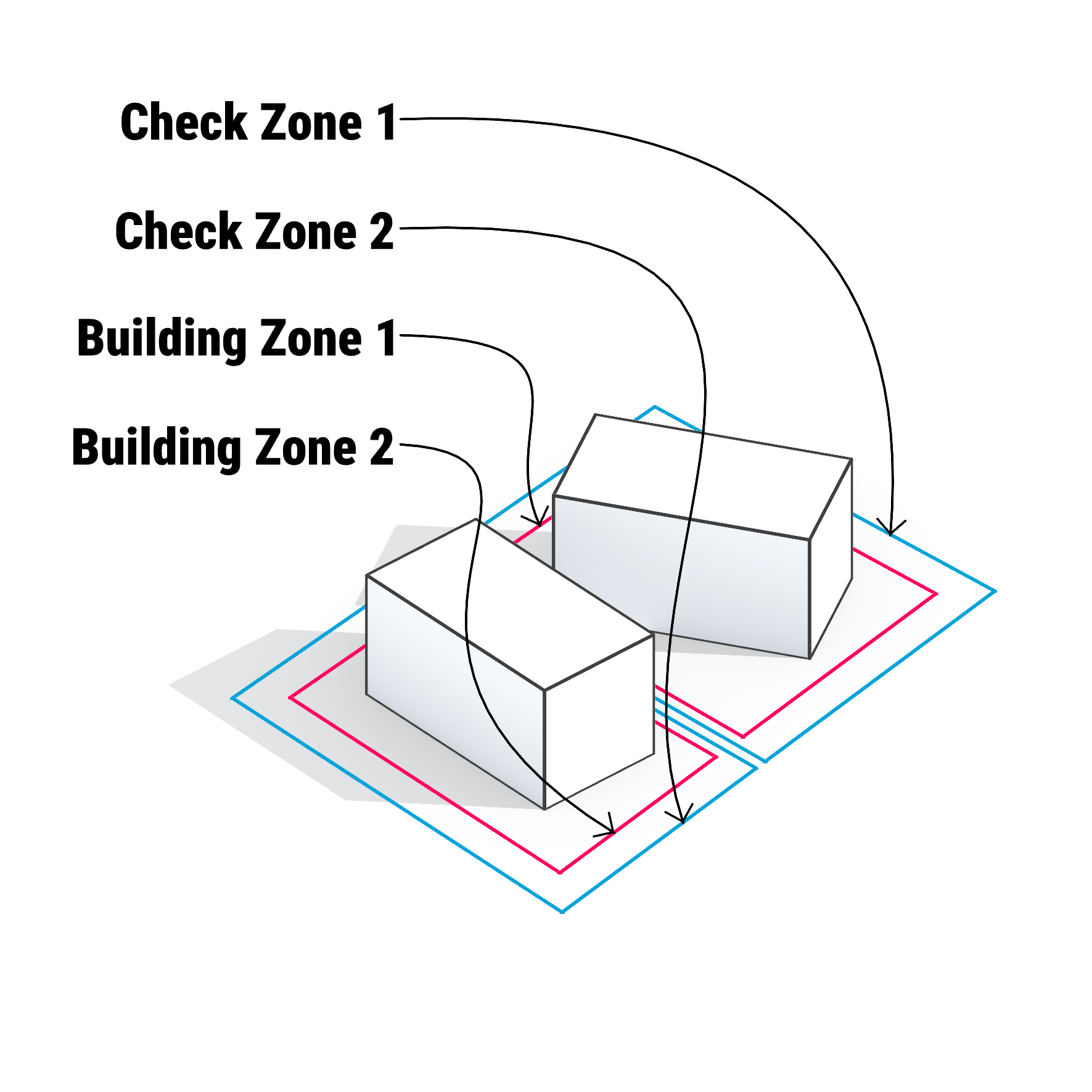
Allows you to set the maximum areas and volumes that are possible to utilize. For example maximum Coverage Area or Intensity. You can have several different CheckZones in your project.
BuildingZone:
Inside the CheckZone you will always have at least one BuildingZone. The BuildingZone can be the same size as the CheckZone or smaller, but it can never be even partially outside of the CheckZone. In the BuildingZone you will set all the architectural parameters that define the geometry of the generated buildings.
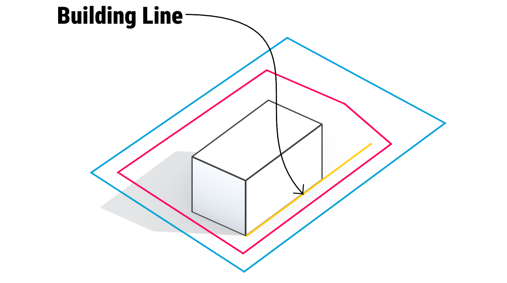
Building Line
If you are required to adjust the buildings to a fixed lines, you can use BuildingLine which will force buildings to be placed with their facade exactly on the spot. It can have multiple vertices forming the polyline.
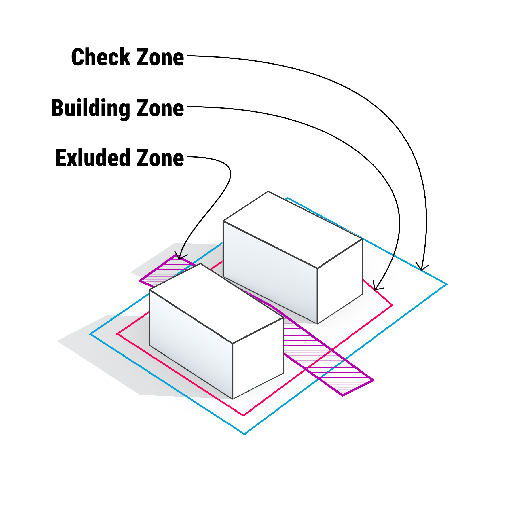
ExcludedZone:
The area where the buildings will never be placed even partially. ExcludedZone can be drawn in any way, so it can intersect with other zones, forbidding from genereting buildings inside it.

DRAWING THE SITE
Use our map portal to easily prepare the site geometry online
or
Use the CAD software of your choosing
Using the built-in map portal
Using the CAD software
You can prepare DXF file in any CAD software. For detailed instructions check the link below:
How to prepare a CAD dxf file.
02 SITE INPUT
In the pameters column on the right side of the window, enter the parameter values for your investment. This information is necessary for the operation of Kolega.
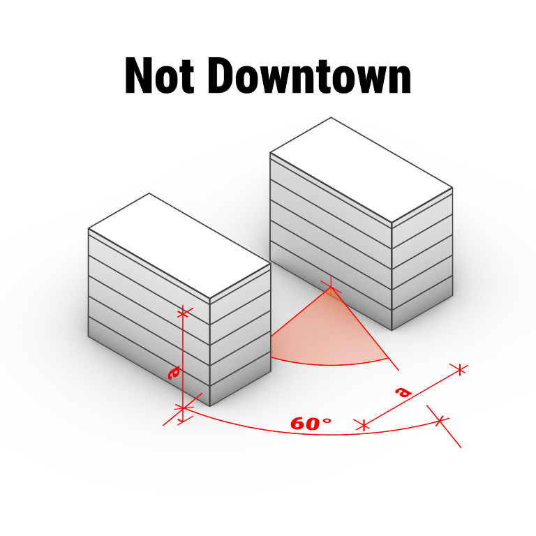
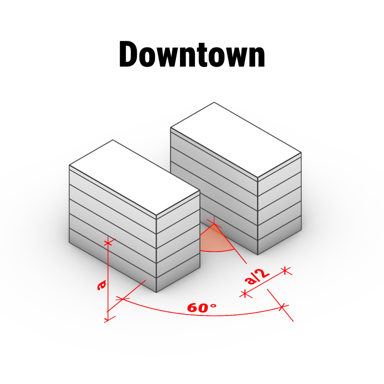
Enable the option when a ptoject is located in a dense urban center. Activating this option allows a wall with windows to be positioned at a distance equal to half the height of the opposite building. The height is measured from the window sill of the analyzed building to the highest point of the opposite building.
If this option is disabled, the minimum distance between a wall with windows and the neighboring building must be at least equal to the height of the opposite building.
These settings do not affect the calculation of direct sunlight. To determine the minimum duration of direct sunlight exposure, go to Sunlight Settings in “02 Site Input”.
Low/High Density Development
Is the investment located in the downtown area. The downtown area has less rigorous requirements for access to sky light.
Latitude, Longitude
Location of the plot. It is necessary to specify these values accurately because direct sunlight will be calculated based on this.
Verify coordinates
By clicking this button you can check on the map whether the entered longitude and latitude correspond to the selected plot.
Analyze Obstruction
You can decide if the Obstruction analysis is performed during the solutions generation process. If toggle button is selected “to the right side”, it means that
Analyze Sunlight
You can decide if the Sunlight analysis is performed during the solutions generation process. If toggle button is selected “to the right side”, it means that
Preset:
Settings for time zone and minimum direct sunlight requirement.
Preset or custom time requirements for daylight analysis (date, time and span).Note: Due to summer time changes in some time zones, Kolega is aware of daylight saving time.
Sunlight Settings:
Timezone:
Time zone where the plot is located.
Time spans:
To specify the time interval in which the minimum direct sunlight will be checked, you need to specify: the date, the minimum required number of hours and the time interval in which this will be analyzed.
You can add a few time periods to include in the calculation.
If several time spans are added, the minimum requirements will have to be met in all of them.
Failure to meet the requirements in one of the time slots means failure to provide minimum insolation.
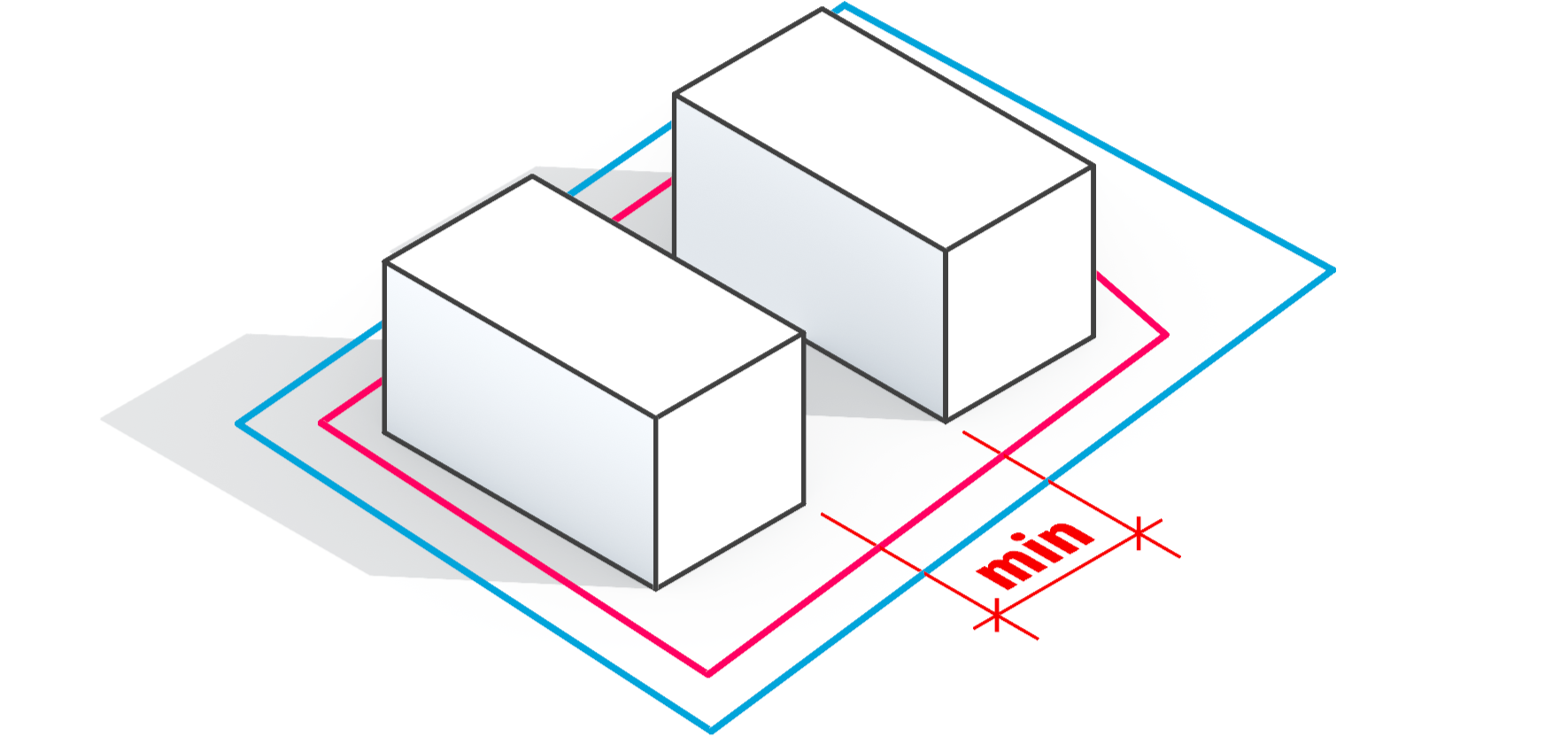
Minimum Distance Between Buildings
You can set the minimal distance that will be unbuilt between the generated buildings. If set to “0” Sunlight and Obscuring analysis will still influence the distances between buildings.
Flats related settings on area calculation.
Flat area ratio:
The area of the apartments, reduced by the walls and internal utility shafts.
Area Settings:
03 ARCHITECTURE
Checkzone:
Maximum building coverage ratio
The maximum area of the CheckZone that can be covered by the buildings. The ratio can be up to 1.0, which means even all the site area can be covered.
Maximum Floor Area Ratio above ground
Value limites the total sum of all building areas which are above the ground level.
If the site area equals 5 000 m2 and the parameter is set to “2”, the total area of all the floors above ground will not be larger than 10 000 m2.
Maximum Floor Area Ratio undergound
Value limites the total sum of all building areas which are under the ground level.
If the site area equals 5 000 m2 and the parameter is set to “1.5”, the total area of all the floors below ground will not be larger than 7 500 m2.
Buildingzone:
Maximum height
Maximum level count
Minimum level count
Roof attic height
Level height
Building length interval
Depth of sectional buildings (building with apartments that have access to sunlight on two sides of the building)
Depth of corridor buildings (building with apartments that have access to sunlight on one side of the building)
Building Orientation Angle - the ability to set the desired building grid direction.
Acceptable angle of building orientation deviation - freedom of grid rotation from the angle set in "Building orientation angle" (both to the left and to the right).
04 GENERATE
Kolega has three building generation modes:
Initial 256 generates solutions, displays 32
Standard 480 generates solutions, displays 48
Extended 640 generates solutions, displays 64
Development generation time may vary depending on the size of the plot and the complexity of the case.
By clicking on the stop and save button, we can stop generation and move to the next step on the “05 Solutions” navigation bar.
05 SOLUTION

On the 05 Solutions screen, you can view, compare, and filter the building layouts generated by Kolega.
Solution Cards
On the left, you will find solution cards. Each card displays:
a visualization of the building arrangement,
key data:
Flats Area: Total area assigned to flats.
General Floor Area: Total usable floor area.
Footprint Area: Ground-level area covered by buildings.
Daylight: Percentage of flats that pass the daylight requirements for the analysis.
Obstructing: Percentage of flats that pass the obstruction requirements for the analysis.
Double-click on any solution card to open and view it in detail.
Generations List
On the right of the solution cards, the list of solution generations is shown. Each item is labeled, and clicking it lets you browse solutions from earlier design stages.
Sorting Solutions
Use the Sorting solutions panel to organize results by:
Flats Area
Footprint Area
Daylight Ratio
Achieved Obstruction Ratio
Select your preferred metric to bring the most relevant solutions to the top.
Solution Filters
Use sliders or checkboxes to filter solutions:
Flats Area: Set minimum area for flats.
Footprint Area: Limit the ground footprint.
Daylight Ratio: Show only solutions meeting a daylight requirement.
Minimum Obstruction Ratio: Exclude solutions with high obstruction.
Check Show starred only to quickly revisit your favorite options. Star solutions directly on the cards by clicking the star icon.
Instructions for Use
Change filters to narrow down options based on project requirements.
Sort to focus on your most important criteria.
Star the best solutions as you review them.
Move between generations to explore how your solutions evolved over time.
Double-click a solution card to open it for a detailed view.
Detailed view:
On this screen, you can thoroughly examine the selected solution in both 3D view and with its detailed properties.
Main Features
3D Visualization
The central area displays a 3D model of your selected solution.
View Controls (bottom of the 3D window)
Use the control panel to zoom, pan, rotate, and reset the view for precise inspection of the design.
Download Function
Download Button
Located in the bottom-left corner (downward arrow), this lets you export your solution directly as:
BIM
DXF
CSV
PDF
Switching Between Views
In the panel to the right of the 3D window, use these options to change what is shown:
Masses: View the overall building forms and their positions.
Flats: See all individual flats and the communication spaces (corridors, stairs, etc.)—this helps to understand flat arrangement.
Obstruction / Daylight: Both these views show flats with the results of their respective analyses.
Obstruction: See which flats pass or fail the obstruction criteria. Points where the analysis was performed are also visible.
Daylight: See which flats meet the daylight requirements and view the analysis points.
Input: Review all the configuration and site data you provided for calculations, such as plot geometry, latitude, longitude, density setting, minimum distances, and sunlight requirements.
General Information Panel
On the right, you will see key project data for reference, including:
Project name
Location (latitude/longitude)
North angle
Density and distance settings
Daylight and obstruction analysis parameters
First daylight interval required by the project
Navigation
Click Back to Solutions List to return to the main list of solutions for easy comparison and selection of other proposals.
Tip
Use the different views to analyze architectural massing, layout, daylight, and obstruction results. Download your files in the desired format to integrate them into your further design or presentation workflow.